Camera
About the Camera Modules
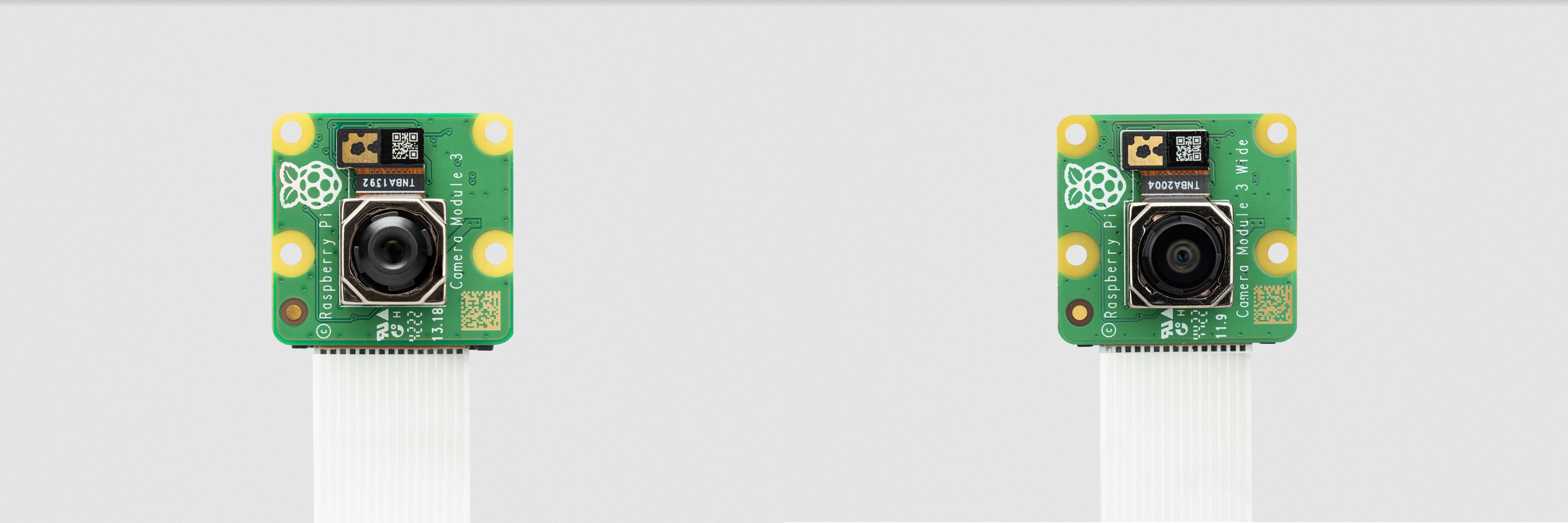
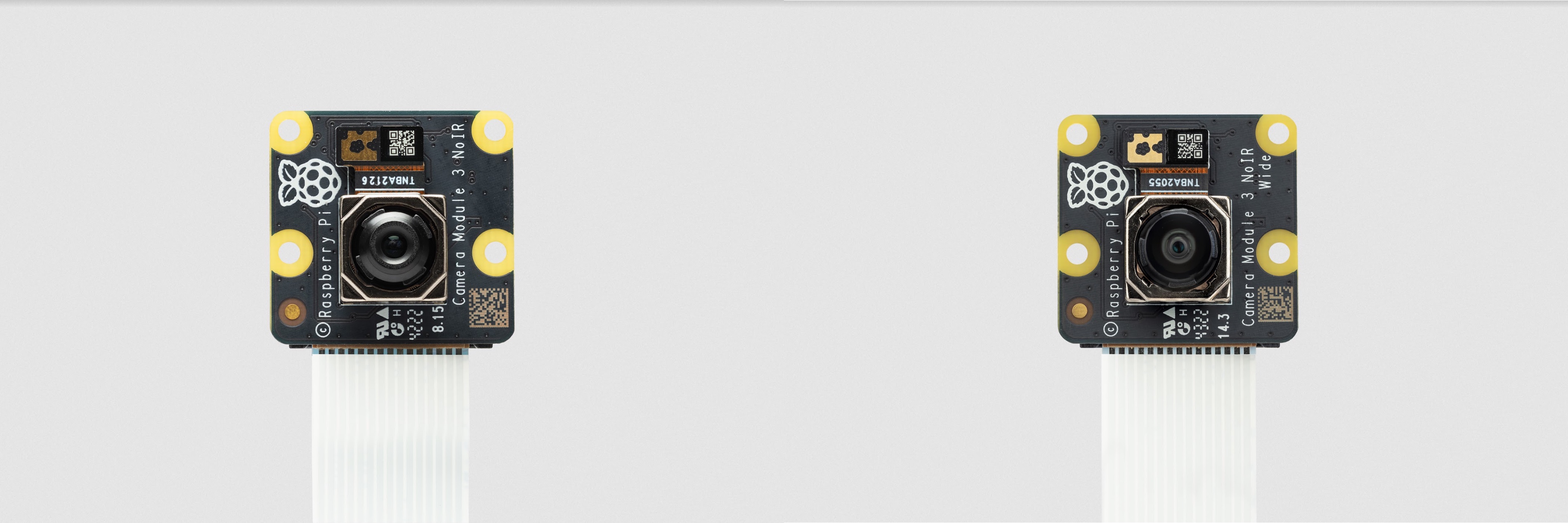
There are now several official Raspberry Pi camera modules. The original 5-megapixel model was released in 2013, it was followed by an 8-megapixel Camera Module 2 which was released in 2016. The latest camera model is the 12-megapixel Camera Module 3 which was released in 2023. The original 5MP device is no longer available from Raspberry Pi.
All of these cameras come in visible light and infrared versions, while the Camera Module 3 also comes as a standard or wide FoV model for a total of four different variants.
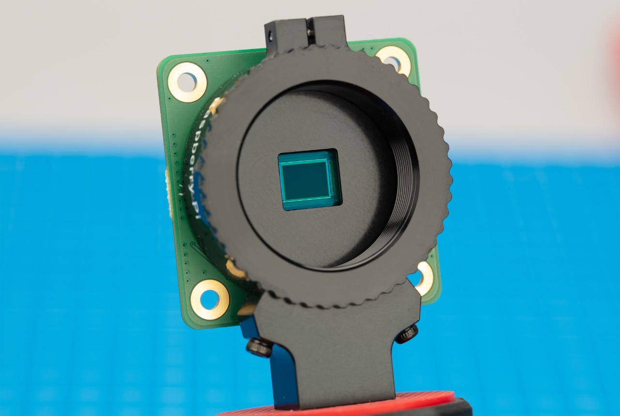
Additionally, a 12-megapixel High Quality Camera with CS- or M12-mount variants for use with external lenses was released in 2020 and 2023 respectively. There is no infrared version of the HQ Camera, however the IR Filter can be removed if required.
The Raspberry Pi AI Camera uses the Sony IMX500 imaging sensor to provide low-latency and high-performance AI capabilities to any camera application. Tight integration with Raspberry Pi’s camera software stack allows users to deploy their own neural network models with minimal effort.
Finally, there is the Global Shutter camera, which was released in 2023. There is no infrared version of the GS Camera, however the IR Filter can be removed if required.

|
Note
|
Raspberry Pi Camera Modules are compatible with all Raspberry Pi computers with CSI connectors - that is, all models except Raspberry Pi 400 and the 2016 launch version of Zero. |
Rolling or Global shutter?
Most digital cameras, including our Camera Modules, use a rolling shutter: they scan the image they’re capturing line-by-line, then output the results. You may have noticed that this can cause distortion effects in some settings; if you’ve ever photographed rotating propeller blades, you’ve probably spotted the image shimmering rather than looking like an object that is rotating. The propeller blades have had enough time to change position in the tiny moment that the camera has taken to swipe across and observe the scene.
A global shutter, like the one on our Global Shutter Camera Module, doesn’t do this. It captures the light from every pixel in the scene at once, so your photograph of propeller blades will not suffer from the same distortion.
Why is this useful? Fast-moving objects, like those propeller blades, are now easy to capture; we can also synchronise several cameras to take a photo at precisely the same moment in time. There are plenty of benefits here, like minimising distortion when capturing stereo images. (The human brain is confused if any movement that appears in the left eye has not appeared in the right eye yet.) The Raspberry Pi Global Shutter Camera can also operate with shorter exposure times - down to 30µs, given enough light - than a rolling shutter camera, which makes it useful for high-speed photography.
|
Note
|
The Global Shutter Camera’s image sensor has a 6.3mm diagonal active sensing area, which is similar in size to Raspberry Pi’s HQ Camera. However, the pixels are larger and can collect more light. Large pixel size and low pixel count are valuable in machine-vision applications; the more pixels a sensor produces, the harder it is to process the image in real time. To get around this, many applications downsize and crop images. This is unnecessary with the Global Shutter Camera and the appropriate lens magnification, where the lower resolution and large pixel size mean an image can be captured natively. |
Install a Raspberry Pi camera
|
Warning
|
Cameras are sensitive to static. Earth yourself prior to handling the PCB. A sink tap or similar should suffice if you don’t have an earthing strap. |
Connect the Camera
The flex cable inserts into the connector labelled CAMERA on the Raspberry Pi, which is located between the Ethernet and HDMI ports. The cable must be inserted with the silver contacts facing the HDMI port. To open the connector, pull the tabs on the top of the connector upwards, then towards the Ethernet port. The flex cable should be inserted firmly into the connector, with care taken not to bend the flex at too acute an angle. To close the connector, push the top part of the connector towards the HDMI port and down, while holding the flex cable in place.
We have created a video to illustrate the process of connecting the camera. The following video shows how to connect the original camera on the original Raspberry Pi 1. The principle is the same for all Raspberry Pi boards with a camera connector, though the Raspberry Pi 5 and all Raspberry Pi Zero models require a different camera cable.
Depending on the model, the camera may come with a small piece of translucent blue plastic film covering the lens. This is only present to protect the lens while it is being mailed to you, and needs to be removed by gently peeling it off.
Prepare the Software
Before proceeding, we recommend ensuring that your kernel, GPU firmware and applications are all up to date. Please follow the instructions on keeping your operating system up to date.
Then, please follow the relevant setup instructions for rpicam-apps, and the Picamera2 Python library.
Hardware Specification
| Camera Module v1 | Camera Module v2 | Camera Module 3 | Camera Module 3 Wide | HQ Camera | AI Camera | GS Camera | |
|---|---|---|---|---|---|---|---|
Net price |
$25 |
$25 |
$25 |
$35 |
$50 |
$70 |
$50 |
Size |
Around 25 × 24 × 9 mm |
Around 25 × 24 × 9 mm |
Around 25 × 24 × 11.5 mm |
Around 25 × 24 × 12.4 mm |
38 × 38 × 18.4mm (excluding lens) |
25 × 24 × 11.9mm |
38 × 38 × 19.8mm (29.5mm with adaptor and dust cap) |
Weight |
3g |
3g |
4g |
4g |
30.4g |
6g |
34g (41g with adaptor and dust cap) |
Still resolution |
5 megapixels |
8 megapixels |
11.9 megapixels |
11.9 megapixels |
12.3 megapixels |
12.3 megapixels |
1.58 megapixels |
Video modes |
1080p30, 720p60 and 640 × 480p60/90 |
1080p47, 1640 × 1232p41 and 640 × 480p206 |
2304 × 1296p56, 2304 × 1296p30 HDR, 1536 × 864p120 |
2304 × 1296p56, 2304 × 1296p30 HDR, 1536 × 864p120 |
2028 × 1080p50, 2028 × 1520p40 and 1332 × 990p120 |
2028 × 1520p30, 4056 × 3040p10 |
1456 × 1088p60 |
Sensor |
OmniVision OV5647 |
Sony IMX219 |
Sony IMX708 |
Sony IMX708 |
Sony IMX477 |
Sony IMX500 |
Sony IMX296 |
Sensor resolution |
2592 × 1944 pixels |
3280 × 2464 pixels |
4608 × 2592 pixels |
4608 × 2592 pixels |
4056 × 3040 pixels |
4056 × 3040 pixels |
1456 × 1088 pixels |
Sensor image area |
3.76 × 2.74 mm |
3.68 × 2.76 mm (4.6 mm diagonal) |
6.45 × 3.63mm (7.4mm diagonal) |
6.45 × 3.63mm (7.4mm diagonal) |
6.287mm × 4.712 mm (7.9mm diagonal) |
6.287mm × 4.712 mm (7.9mm diagonal) |
6.3mm diagonal |
Pixel size |
1.4 µm × 1.4 µm |
1.12 µm × 1.12 µm |
1.4 µm × 1.4 µm |
1.4 µm × 1.4 µm |
1.55 µm × 1.55 µm |
1.55 µm × 1.55 µm |
3.45 µm × 3.45 µm |
Optical size |
1/4" |
1/4" |
1/2.43" |
1/2.43" |
1/2.3" |
1/2.3" |
1/2.9" |
Focus |
Fixed |
Adjustable |
Motorized |
Motorized |
Adjustable |
Adjustable |
Adjustable |
Depth of field |
Approx 1 m to ∞ |
Approx 10 cm to ∞ |
Approx 10 cm to ∞ |
Approx 5 cm to ∞ |
N/A |
Approx 20 cm to ∞ |
N/A |
Focal length |
3.60 mm +/- 0.01 |
3.04 mm |
4.74 mm |
2.75 mmm |
Depends on lens |
4.74 mm |
Depends on lens |
Horizontal Field of View (FoV) |
53.50 +/- 0.13 degrees |
62.2 degrees |
66 degrees |
102 degrees |
Depends on lens |
66 ±3 degrees |
Depends on lens |
Vertical Field of View (FoV) |
41.41 +/- 0.11 degrees |
48.8 degrees |
41 degrees |
67 degrees |
Depends on lens |
52.3 ±3 degrees |
Depends on lens |
Focal ratio (F-Stop) |
F2.9 |
F2.0 |
F1.8 |
F2.2 |
Depends on lens |
F1.79 |
Depends on lens |
Maximum exposure time (seconds) |
3.28 |
11.76 |
112 |
112 |
670.74 |
112 |
15.5 |
Lens Mount |
N/A |
N/A |
N/A |
N/A |
C/CS- or M12-mount |
N/A |
C/CS |
NoIR version available? |
Yes |
Yes |
Yes |
Yes |
No |
No |
No |
|
Note
|
There is some evidence to suggest that the Camera Module 3 may emit RFI at a harmonic of the CSI clock rate. This RFI is in a range to interfere with GPS L1 frequencies (1575 MHz). Please see the thread on Github for details and proposed workarounds. |
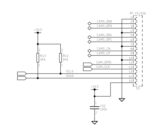
Mechanical Drawings
Available mechanical drawings;
|
Note
|
Board dimensions and mounting-hole positions for Camera Module 3 are identical to Camera Module 2. However, due to changes in the size and position of the sensor module, it is not mechanically compatible with the camera lid for the Raspberry Pi Zero Case. |
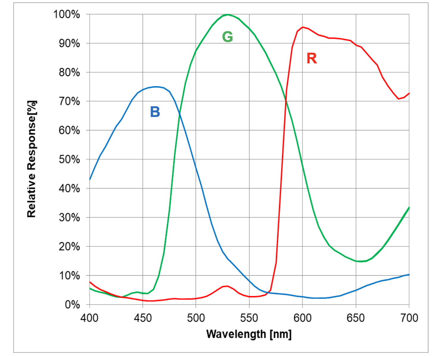
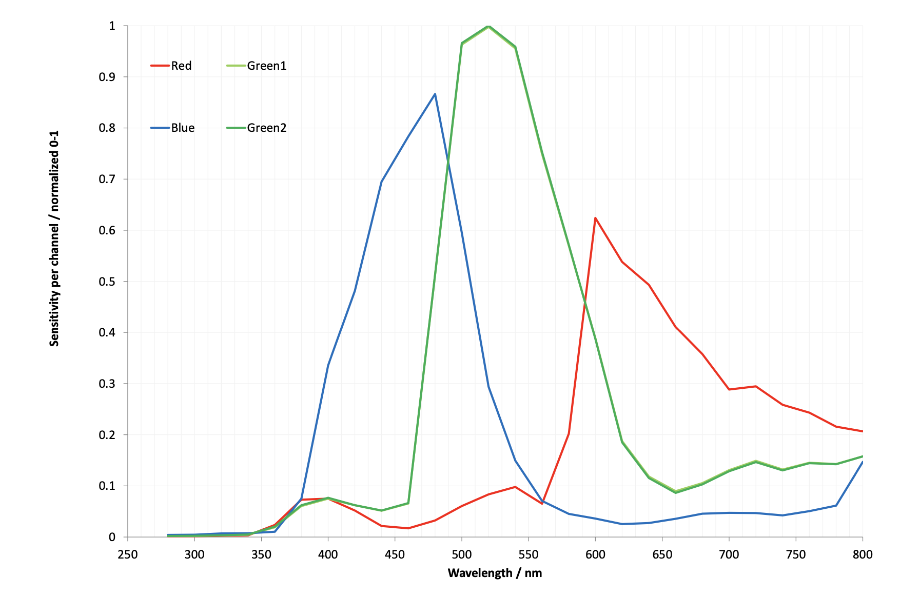
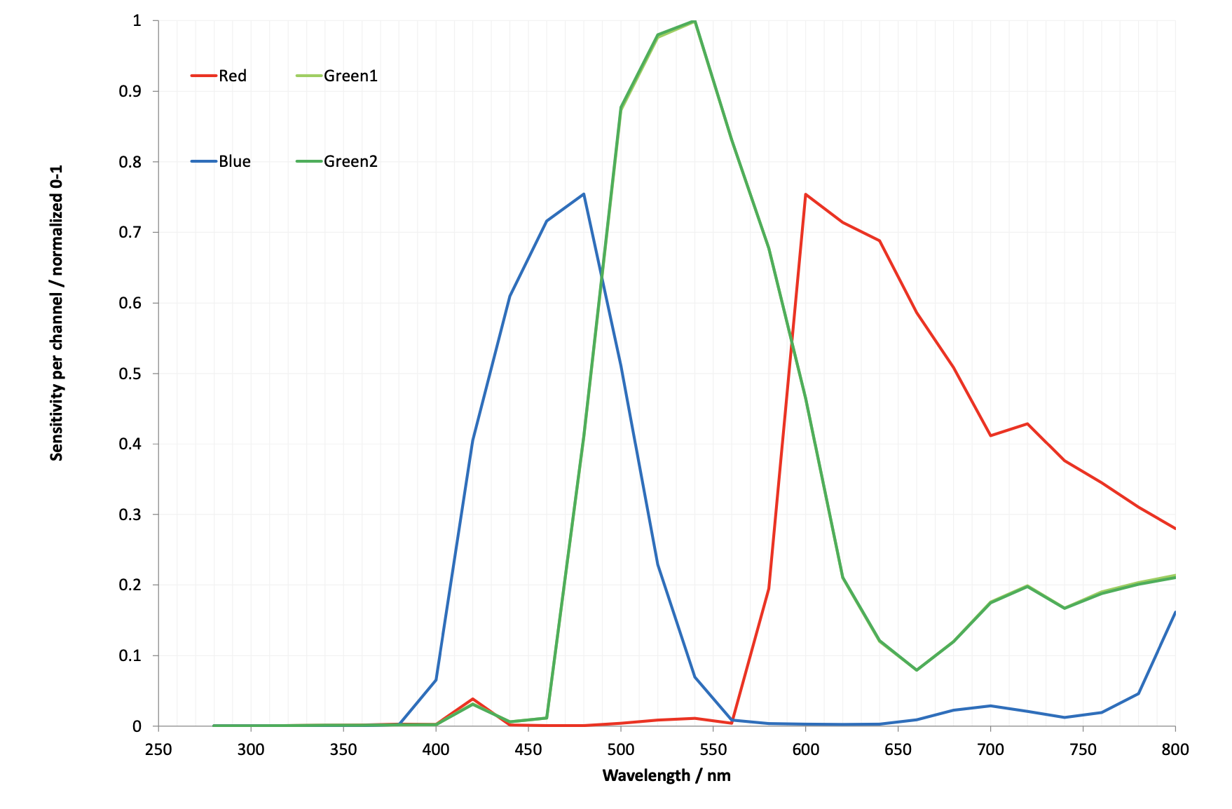
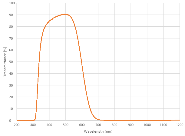
Camera Filters
Some transmission characteristics are available for the Camera Module 3 and the HQ and GS cameras.
|
Note
|
These graphs are available as a PDF. |
IR Filter
Both the High Quality Camera and Global Shutter Camera contain an IR filter to reduce the camera’s sensitivity to infrared light and help outdoor photos look more natural. However, you may remove the filter to:
-
Enhance colours in certain types of photography, such as images of plants, water, and the sky
-
Provide night vision in a location that is illuminated with infrared light
Filter Removal
|
Warning
|
This procedure cannot be reversed: the adhesive that attaches the filter will not survive being lifted and replaced, and while the IR filter is about 1.1mm thick, it may crack when it is removed. Removing it will void the warranty on the product. |
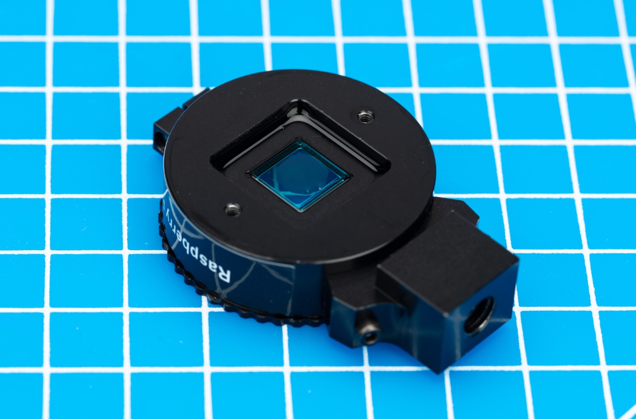
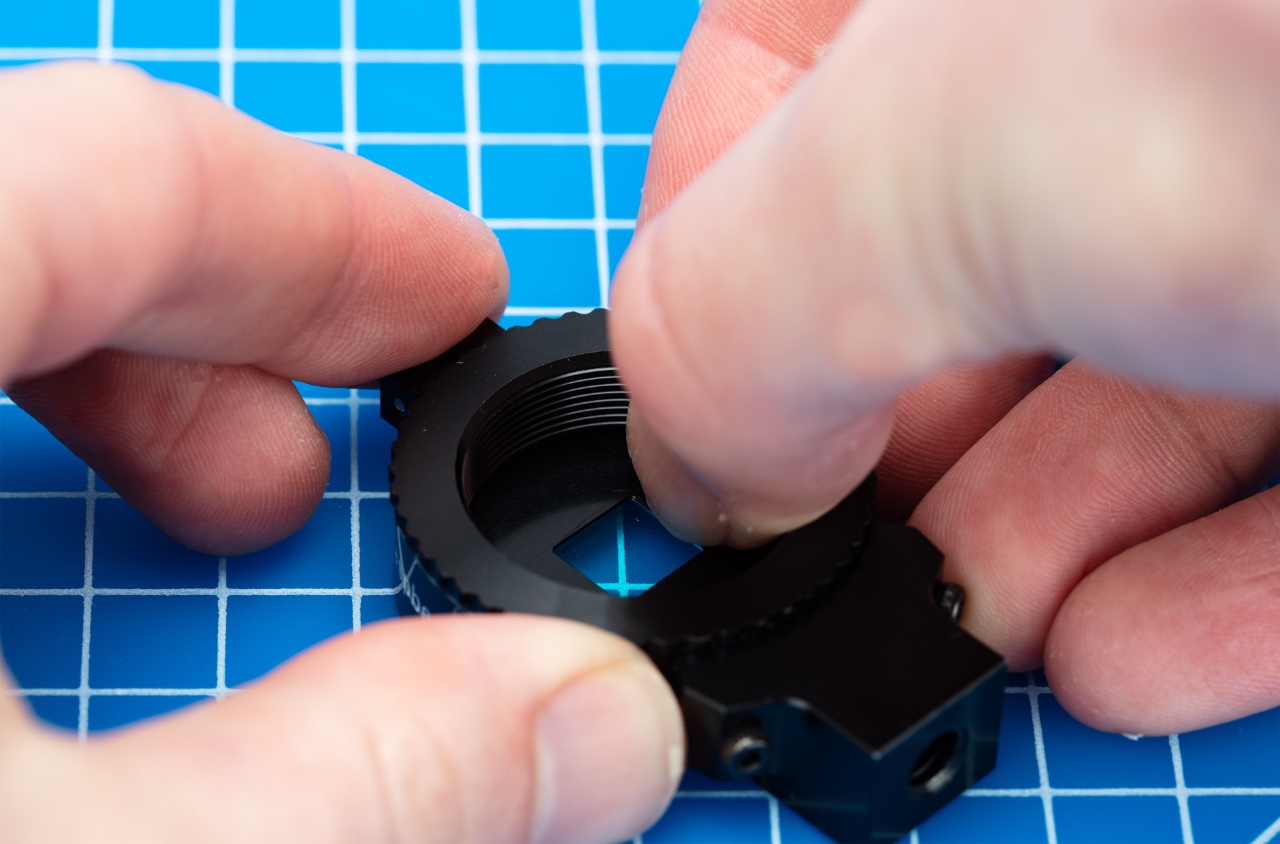
You can remove the filter from both the HQ and GS cameras. The HQ camera is shown in the demonstration below.
|
Note
|
Make sure to work in a clean and dust-free environment, as the sensor will be exposed to the air. |
-
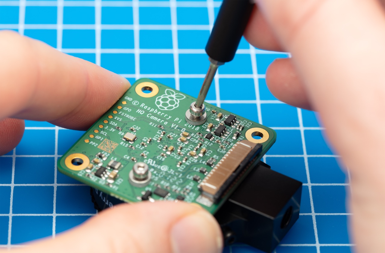
Unscrew the two 1.5 mm hex lock keys on the underside of the main circuit board. Be careful not to let the washers roll away.
-
There is a gasket of slightly sticky material between the housing and PCB which will require some force to separate. You may try some ways to weaken the adhesive, such as a little isopropyl alcohol and/or heat (~20-30 C).
-
Once the adhesive is loose, lift up the board and place it down on a very clean surface. Make sure the sensor does not touch the surface.
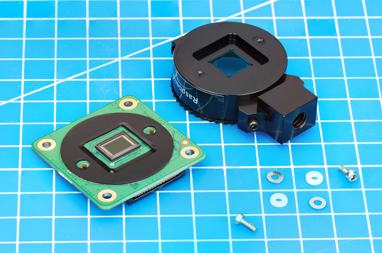
-
Face the lens upwards and place the mount on a flat surface.
-
To minimise the risk of breaking the filter, use a pen top or similar soft plastic item to push down on the filter only at the very edges where the glass attaches to the aluminium. The glue will break and the filter will detach from the lens mount.
-
Given that changing lenses will expose the sensor, at this point you could affix a clear filter (for example, OHP plastic) to minimize the chance of dust entering the sensor cavity.
-
Replace the main housing over the circuit board. Be sure to realign the housing with the gasket, which remains on the circuit board.
-
Apply the nylon washer first to prevent damage to the circuit board.
-
Next, fit the steel washer, which prevents damage to the nylon washer. Screw down the two hex lock keys. As long as the washers have been fitted in the correct order, they do not need to be screwed very tightly.
|
Note
|
It is likely to be difficult or impossible to glue the filter back in place and return the device to functioning as a normal optical camera. |
Recommended Lenses
The following lenses are recommended for use with our HQ and GS cameras.
|
Note
|
While the HQ Camera is available in both C/CS- and M12-mount versions, the GS Camera is available only with a C/CS-mount. |
C/CS Lenses
We recommend two lenses, a 6mm wide angle lens and a 16mm telephoto lens. These lenses should be available from your nearest Authorised Reseller.
| 16mm telephoto | 6mm wide angle | ||
|---|---|---|---|
Resolution |
10MP |
3MP |
|
Image format |
1" |
1/2" |
|
Aperture |
F1.4 to F16 |
F1.2 |
|
Mount |
C |
CS |
|
Field of View H°×V° (D°) |
HQ |
22.2°×16.7° (27.8°) |
55°×45° (71°) |
GS |
17.8°×13.4° (22.3) |
45°×34° (56°) |
|
Back focal length |
17.53mm |
7.53mm |
|
M.O.D. |
0.2m |
0.2m |
|
Dimensions |
φ39.00×50.00mm |
φ30×34mm |
|
M12 Lenses
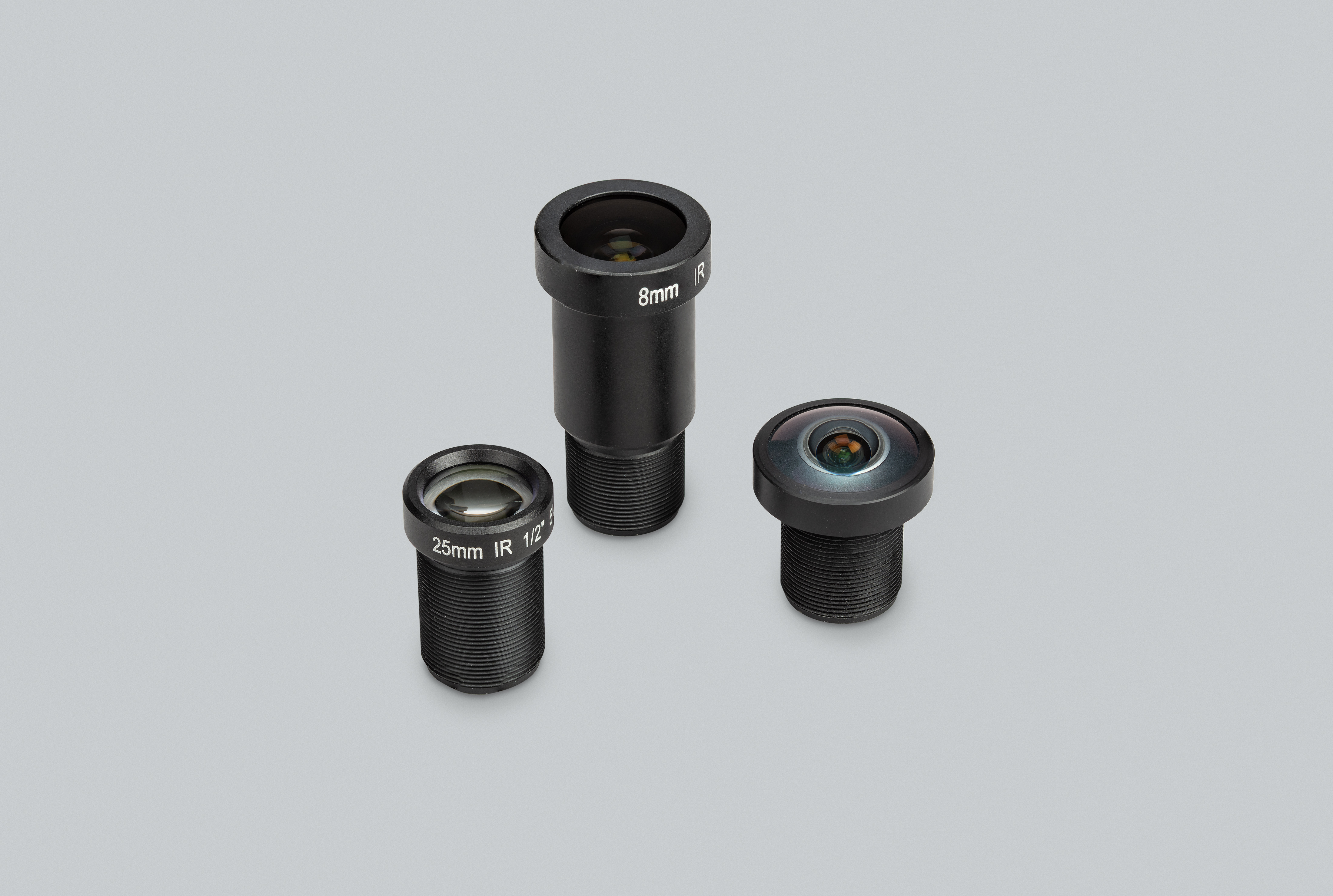
We recommend three lenses manufactured by Gaojia Optotech. These lenses should be available from your nearest Authorised Reseller.
| 8mm | 25mm | Fish Eye | ||
|---|---|---|---|---|
Resolution |
12MP |
5MP |
15MP |
|
Image format |
1/1.7" |
1/2" |
1/2.3" |
|
Aperture |
F1.8 |
F2.4 |
F2.5 |
|
Mount |
M12 |
|||
HQ Field of View H°×V° (D°) |
49°×36° (62°) |
14.4°×10.9° (17.9)° |
140°×102.6° (184.6°) |
|
Synchronous Captures
Both the HQ Camera and the Global Shutter Camera, have support for synchronous captures. Making use of the XVS pin (Vertical Sync) allows one camera to pulse when a frame capture is initiated. The other camera can then listen for this sync pulse, and capture a frame at the same time as the other camera.
Using the HQ Camera
For correct operation, both cameras require a 1.65V pull up voltage on the XVS line, which is created by a potential divider through the 3.3V and GND pins on the Raspberry Pi.
Create a potential divider from two 10kΩ resistors to 3.3V and ground (to make 1.65V with an effective source impedance of 5kΩ). This can be connected to either Raspberry Pi.
Solder the GND and XVS test points of each HQ Camera board to each other.
Connect the XVS wires to the 1.65V potential divider pull-up.
Boot up both Raspberry Pis
The file /sys/module/imx477/parameters/trigger_mode determines which board outputs pulses, or waits to receive pulses (source and sink).
This parameter can only be altered in superuser mode.
Run the following commands to configure the sink:
$ sudo su
$ echo 2 > /sys/module/imx477/parameters/trigger_mode
$ exit
Run the following commands to configure the source:
$ sudo su
$ echo 1 > /sys/module/imx477/parameters/trigger_mode
$ exit
Run the following command to start the sink:
$ rpicam-vid --frames 300 --qt-preview -o sink.h264Run the following command to start the source:
$ rpicam-vid --frames 300 --qt-preview -o source.h264Frames should be synchronous. Use --frames to ensure the same number of frames are captured, and that the recordings are exactly the same length.
Running the sink first ensures that no frames are missed.
|
Note
|
The potential divider is needed to pull up the XVS pin to high whilst the source is in an idle state. This ensures that no frames are created or lost upon startup. The source whilst initialising goes from LOW to HIGH which can trigger a false frame. |
Use the GS Camera
|
Note
|
The Global Shutter (GS) camera can also be operated in a synchronous mode. However, the source camera will record one extra frame. A much better alternative method to ensure that both cameras capture the same amount of frames is to use the external trigger method. |
To operate as source and sink together, the Global Shutter Cameras also require connection of the XHS (horizontal sync) pins together. However, these do not need connection to a pullup resistor.
The wiring setup is identical to the HQ Camera method, except that you will also need to connect the XHS pins together.
Create a potential divider from two 10kΩ resistors to 3.3V and ground (to make 1.65V with an effective source impedance of 5kΩ). This can be connected to either Raspberry Pi.
Solder 2 wires to the XVS test points on each board and connect both of these wires together to the 1.65V potential divider.
Solder the GND of each Camera board to each other. Also solder 2 wires to the XHS test points on each board and connect these. No pullup is needed for XHS pin.
On the boards that you wish to act as sinks, solder the two halves of the MAS pad together. This tells the sensor to act as a sink, and will wait for a signal to capture a frame.
Boot up source and sink
Run the following command to start the sink:
$ rpicam-vid --frames 300 -o sync.h264Due to the limitations of the IMX296 sensor, the sink cannot record exactly the same number of frames as the source. The source records one extra frame before the sink starts recording. Because of this, you need to specify that the sink records one less frame with the --frames option.
Wait at least two seconds before you start the source.
After waiting two seconds, run the following command to start the source:
$ rpicam-vid --frames 299 -o sync.h264Because the sink and source record a different number of frames, use ffmpeg to resync the videos. By dropping the first frame from the source, we then get two recordings with the same starting point and frame length:
$ ffmpeg -i source.h264 -vf select="gte(n\, 1)" source.h264External Trigger on the GS Camera
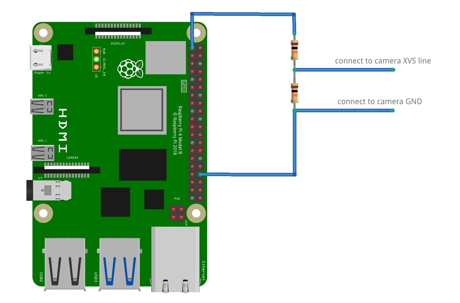
The Global Shutter (GS) camera can be triggered externally by pulsing the external trigger (denoted on the board as XTR) connection on the board. Multiple cameras can be connected to the same pulse, allowing for an alternative way to synchronise two cameras.
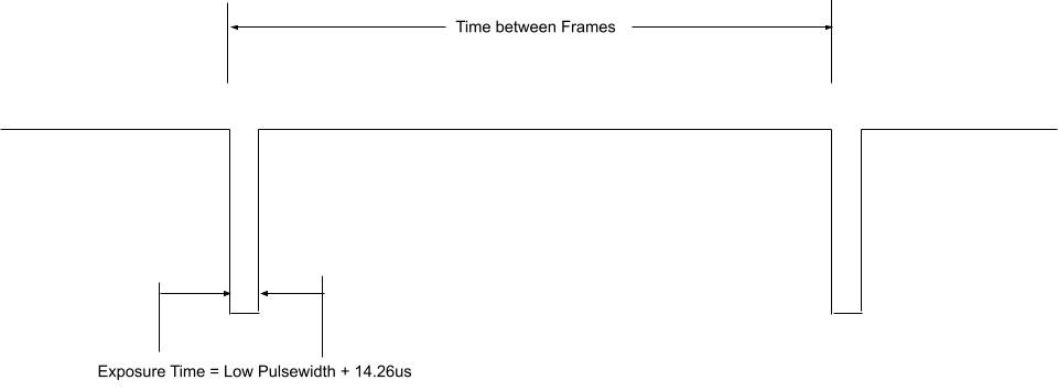
The exposure time is equal to the low pulse-width time plus an additional 14.26us. i.e. a low pulse of 10000us leads to an exposure time of 10014.26us. Framerate is directly controlled by how often you pulse the pin. A PWM frequency of 30Hz will lead to a framerate of 30 frames per second.
Preparation
|
Warning
|
This modification includes removing an SMD soldered part. You should not attempt this modification unless you feel you are competent to complete it. When soldering to the Camera board, please remove the plastic back cover to avoid damaging it. |
If your board has transistor Q2 fitted (shown in blue on the image below), then you will need to remove R11 from the board (shown in red). This connects GP1 to XTR and without removing R11, the camera will not operate in external trigger mode. The location of the components is displayed below.

Next, solder a wire to the touchpoints of XTR and GND on the GS Camera board. Note that XTR is a 1.8V input, so you may need a level shifter or potential divider.
We can use a Raspberry Pi Pico to provide the trigger. Connect any Pico GPIO pin (GP28 is used in this example) to XTR via a 1.5kΩ resistor. Also connect a 1.8kΩ resistor between XTR and GND to reduce the high logic level to 1.8V. A wiring diagram is shown below.

Boot up the Raspberry Pi with the camera connected.
Enable external triggering through superuser mode:
$ sudo su
$ echo 1 > /sys/module/imx296/parameters/trigger_mode
$ exit
Raspberry Pi Pico MicroPython Code
from machine import Pin, PWM

from time import sleep

pwm = PWM(Pin(28))

framerate = 30
shutter = 6000  # In microseconds

frame_length = 1000000 / framerate
pwm.freq(framerate)

pwm.duty_u16(int((1 - (shutter - 14) / frame_length) * 65535))
The low pulse width is equal to the shutter time, and the frequency of the PWM equals the framerate.
|
Note
|
In this example, Pin 28 connects to the XTR touchpoint on the GS camera board. |
Operation
Run the code on the Pico, and set the camera running:
$ rpicam-hello -t 0 --qt-preview --shutter 3000Every time that the Pico pulses the pin, it should generate a frame. To control the framerate, vary the duration between pulses.
|
Note
|
When running rpicam-apps, always specify a fixed shutter duration to ensure the AGC does not adjust the camera’s shutter speed. The duration does not matter, since it is actually controlled by the external trigger pulse.
|