Touch Display 触摸屏
Raspberry Pi Touch Display
The Raspberry Pi Touch Display is an LCD display that connects to the Raspberry Pi using a DSI connector and GPIO connector.

The Touch Display is compatible with all models of Raspberry Pi, except Raspberry Pi Zero and Zero 2 W, which lack a DSI connector. The earliest Raspberry Pi models lack appropriate mounting holes, requiring additional mounting hardware to fit the stand-offs on the display PCB.
The display has the following key features:
-
800×480px RGB LCD display
-
24-bit colour
-
Industrial quality: 140 degree viewing angle horizontal, 120 degree viewing angle vertical
-
10-point multi-touch touchscreen
-
PWM backlight control and power control over I2C interface
-
Metal-framed back with mounting points for Raspberry Pi display conversion board and Raspberry Pi
-
Backlight lifetime: 20000 hours
-
Operating temperature: -20 to +70 degrees centigrade
-
Storage temperature: -30 to +80 degrees centigrade
-
Contrast ratio: 500
-
Average brightness: 250 cd/m2
-
Viewing angle (degrees):
-
Top - 50
-
Bottom - 70
-
Left - 70
-
Right - 70
-
-
Power requirements: 200mA at 5V typical, at maximum brightness.
-
Outer dimensions: 192.96 × 110.76mm
-
Viewable area: 154.08 × 85.92mm
Mount the Touch Display
You can mount a Raspberry Pi to the back of the Touch Display using its stand-offs and then connect the appropriate cables. You can also mount the Touch Display in a separate chassis if you have one available. The connections remain the same, though you may need longer cables depending on the chassis.
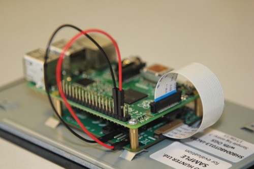
Connect one end of the Flat Flexible Cable (FFC) to the RPI-DISPLAY port on the Touch Display PCB. The silver or gold contacts should face away from the display. Then connect the other end of the FFC to the DISPLAY port on the Raspberry Pi. The contacts on this end should face inward, towards the Raspberry Pi.
If the FFC is not fully inserted or positioned correctly, you will experience issues with the display. You should always double check this connection when troubleshooting, especially if you don’t see anything on your display, or the display shows only a single colour.
|
Note
|
A mechanical drawing of the Touch Display is available for download. |
Power the Touch Display
We recommend using the Raspberry Pi’s GPIO to provide power to the Touch Display. Alternatively, you can power the display directly with a separate micro USB power supply.
Power from a Raspberry Pi
To power the Touch Display using a Raspberry Pi, you need to connect two jumper wires between the 5V and GND pins on Raspberry Pi’s GPIO and the 5V and GND pins on the display, as shown in the following illustration.
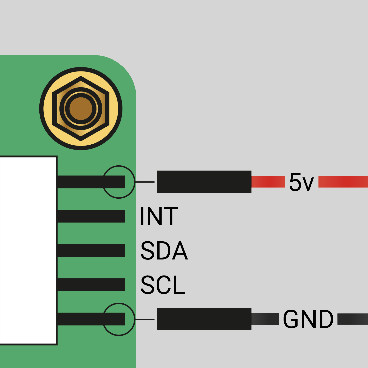
GND pinsBefore you begin, make sure the Raspberry Pi is powered off and not connected to any power source. Connect one end of the black jumper wire to pin six (GND) on the Raspberry Pi and one end of the red jumper wire to pin four (5V). If pin six isn’t available, you can use any other open GND pin to connect the black wire. If pin four isn’t available, you can use any other 5V pin to connect the red wire, such as pin two.

Next, connect the other end of the black wire to the GND pin on the display and the other end of the red wire to the 5V pin on the display. Once all the connections are made, you should see the Touch Display turn on the next time you turn on your Raspberry Pi.
Use the other three pins on the Touch Display to connect the display to an original Raspberry Pi 1 Model A or B. Refer to our documentation on legacy support for more information.
|
Note
|
To identify an original Raspberry Pi, check the GPIO header connector. Only the original model has a 26-pin GPIO header connector; subsequent models have 40 pins. |
Power from a micro USB supply
If you don’t want to use a Raspberry Pi to provide power to the Touch Display, you can use a micro USB power supply instead. We recommend using the Raspberry Pi 12.5W power supply to make sure the display runs as intended.
Do not connect the GPIO pins on your Raspberry Pi to the display if you choose to use micro USB for power. The only connection between the two boards should be the Flat Flexible Cable.
|
Warning
|
When using a micro USB cable to power the display, mount it inside a chassis that blocks access to the display’s PCB during usage. |
Use an on-screen keyboard
Raspberry Pi OS Bookworm and later include the Squeekboard on-screen keyboard by default. When a touch display is attached, the on-screen keyboard should automatically show when it is possible to enter text and automatically hide when it is not possible to enter text.
For applications which do not support text entry detection, use the keyboard icon at the right end of the taskbar to manually show and hide the keyboard.
You can also permanently show or hide the on-screen keyboard in the Display tab of Raspberry Pi Configuration or the Display section of raspi-config.
|
Tip
|
In Raspberry Pi OS releases prior to Bookworm, use matchbox-keyboard instead. If you use the wayfire desktop compositor, use wvkbd instead.
|
Change screen orientation
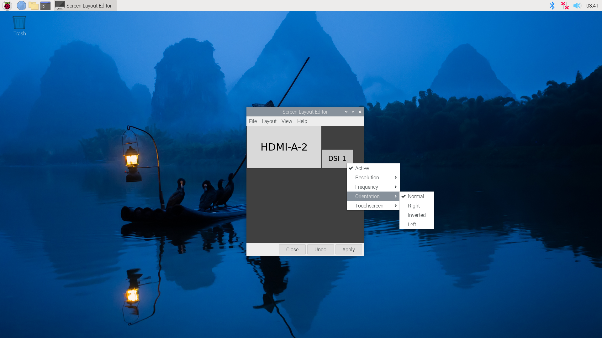
If you want to physically rotate the display, or mount it in a specific position, select Screen Configuration from the Preferences menu. Right-click on the touch display rectangle (likely DSI-1) in the layout editor, select Orientation, then pick the best option to fit your needs.
Rotate screen without a desktop
To set the screen orientation on a device that lacks a desktop environment, edit the /boot/firmware/cmdline.txt configuration file to pass an orientation to the system. Add the following line to cmdline.txt:
video=DSI-1:800x480@60,rotate=<rotation-value>Replace the <rotation-value> placeholder with one of the following values, which correspond to the degree of rotation relative to the default on your display:
-
0 -
90 -
180 -
270
For example, a rotation value of 90 rotates the display 90 degrees to the right. 180 rotates the display 180 degrees, or upside-down.
|
Note
|
It is not possible to rotate the DSI display separately from the HDMI display with cmdline.txt. When you use DSI and HDMI simultaneously, they share the same rotation value.
|
Rotate touch input
|
Warning
|
Rotating touch input via device tree can cause conflicts with your input library. Whenever possible, configure touch event rotation in your input library or desktop. |
Rotation of touch input is independent of the orientation of the display itself. To change this you need to manually add a dtoverlay instruction in /boot/firmware/config.txt. Add the following line at the end of config.txt:
dtoverlay=vc4-kms-dsi-7inch,invx,invyThen, disable automatic display detection by removing the following line from config.txt, if it exists:
display_auto_detect=1Touch Display device tree option reference
The vc4-kms-dsi-7inch overlay supports the following options:
| DT parameter | Action |
|---|---|
|
Sets X resolution (default 800) |
|
Sets Y resolution (default 480) |
|
Invert X coordinates |
|
Invert Y coordinates |
|
Swap X and Y coordinates |
|
Disables the touch overlay totally |
To specify these options, add them, separated by commas, to your dtoverlay line in /boot/firmware/config.txt. Boolean values default to true when present, but you can set them to false using the suffix "=0". Integer values require a value, e.g. sizey=240. For instance, to set the X resolution to 400 pixels and invert both X and Y coordinates, use the following line:
dtoverlay=vc4-kms-dsi-7inch,sizex=400,invx,invyLegacy Support
|
Warning
|
These instructions are for the original Raspberry Pi, Model A, and B, boards only. To identify an original Raspberry Pi, check the GPIO header connector. Only the original model has a 26-pin GPIO header connector; subsequent models have 40 pins. |
The DSI connector on both the Raspberry Pi 1 Model A and B boards does not have the I2C connections required to talk to the touchscreen controller and DSI controller. To work around this, use the additional set of jumper cables provided with the display kit. Connect SCL/SDA on the GPIO header to the horizontal pins marked SCL/SDA on the display board. Power the Model A/B via the GPIO pins using the jumper cables.
DSI display autodetection is disabled by default on these boards. To enable detection, add the following line to the /boot/firmware/config.txt file:
ignore_lcd=0Power the setup via the PWR IN micro-USB connector on the display board. Do not power the setup via the Raspberry Pi’s micro-USB port. This will exceed the input polyfuse’s maximum current rating, since the display consumes approximately 400mA.